








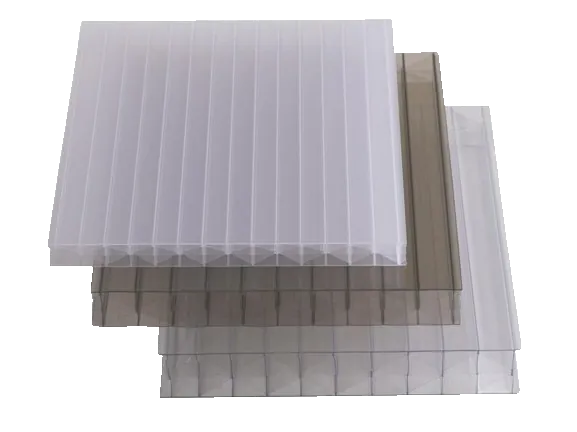
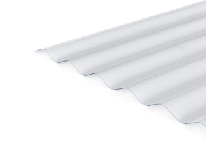
PVC Corrugated Roofing Sheets
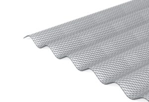
Polycarbonate Corrugated Roofing Sheets
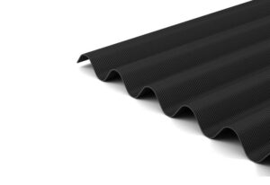


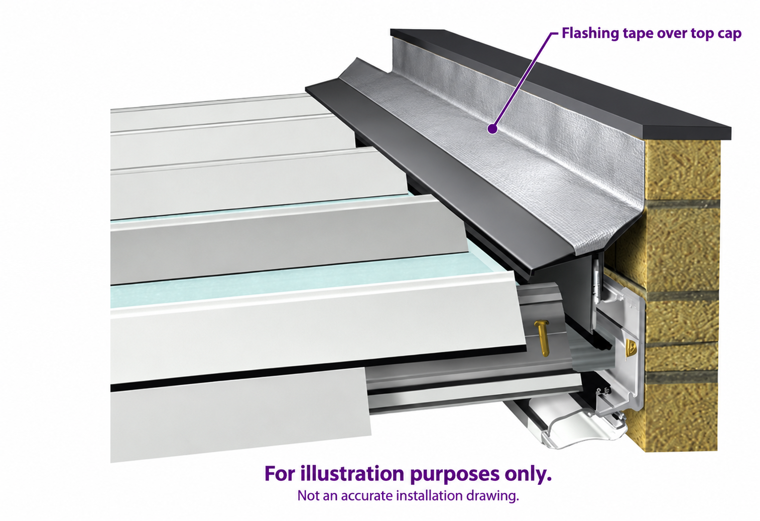
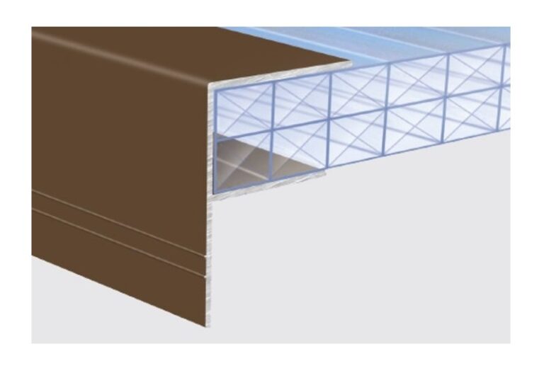
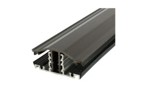
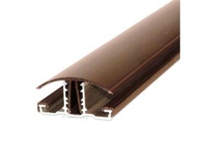
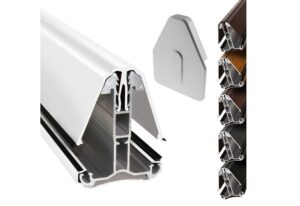
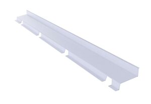
Our Self Supported Wall Plate connects compatible self supported glazing bars to the host wall at the upper end of a lean-to roof. It is used as part of the roof assembly for structures such as lean-to canopies and carports.
The wall plate is a component of the roofing system, rather than a finished, weatherproof wall junction. Suitable flashing must be installed over the top to complete the installation and protect the junction between the roof and wall.
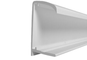
The wall plate has an underclad and a top cap. These serve different purposes and are not necessarily supplied in the same colour.
| Wall plate ordered | Underclad colour | Top cap colour |
|---|---|---|
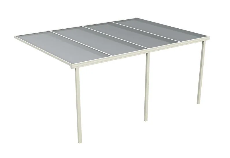
| White | White | White |
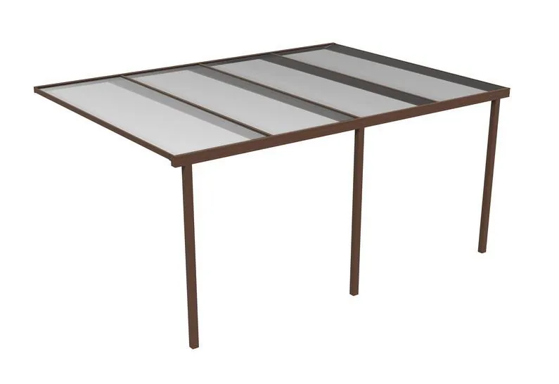
| Brown | Brown | Grey |
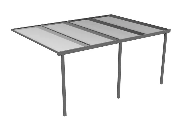
| Grey | Grey | Grey |
Ordering brown? Your wall plate will have a brown underclad and a grey top cap. A brown top cap is not available. The brown underclad provides the colour finish seen from inside or beneath the structure.
The wall plate profile does not sit flush against the host wall to create a continuous weather-tight seal. Although the assembly incorporates seals, these do not replace the flashing required at the wall junction.
Flashing bridges this junction and directs rainwater from the wall onto the roof surface, helping prevent water from tracking behind the wall plate.
A bead of sealant alone is not a suitable substitute for flashing. The junction needs a properly formed flashing detail that covers the top cap and sheds water onto the roof.
We recommend suitable lead flashing, correctly specified and installed for the roof and wall construction.
The flashing should be securely detailed into the host wall and dressed over the wall plate’s top cap to provide effective weather protection. Its coverage must suit the roof pitch and profile, allowing water to drain onto the roof without leaving exposed gaps.
Any alternative flashing system must be suitable for this particular wall-to-roof junction and compatible with the roofing materials. Follow the roofing system and flashing manufacturer’s installation guidance, including requirements for overlap, fixing and movement.
The installation drawing identifies:
| Connection | Fixing size shown |
|---|---|
| Glazing bar to wall plate | M6 × 20mm |
| Glazing bar to front/eaves beam | M6 × 35mm |
These are the bar connection fixings, rather than the masonry fixings used to attach the wall plate to the building. Use the correct compatible bolts, nuts and washers for the system, following the supplier’s installation specification.
The wall plate must be secured through its structural aluminium profile into a suitable load-bearing wall. The drawings do not specify the diameter, length or spacing of these wall fixings.
Suitable structural masonry screws or anchors may be appropriate, but the correct fixing depends on the wall material, its condition, the required embedment depth and the loads from the roof. Any render or other surface finish must also be allowed for when selecting the fixing length.
Your installer should select fixings with manufacturer-confirmed suitability and load capacity for the actual substrate and application. A single screw size cannot be recommended for every installation.
Fixtures and fittings are not included. Installation is recommended for skilled DIYers or tradespeople.
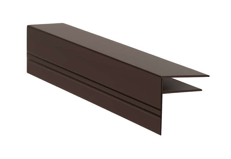





 Description